Hyperion for Desktop
bias lighting The Hyperion package installs with a server and several clients to handle screen capture. I recommend using Hyperion.ng (next generation) as it’s far easier to configure. The classic edition depends on a standalone configuration generator (HyperCon).
Parts
To determine the power supply you’ll need, it’s helpful to know most strips are 60 LEDS per meter and each WS2812b can consume 0.06 amps at full brightness. I used 3 meters (182 LEDs) for my 40" display and needed a 12A power supply.
- WS2812b Strip with Adhesive
- Arduino Nano Clone
- 5V Power Supply
- 330Ω resistor
- Power Cord (grounded)
- 28 AWG wire to connect strip at corners.
Tools
- Soldering Iron
- Multimeter
- Wire strippers
- Scissors
Software
- Hyperion.ng
- Arduino IDE
Instruction
I suggest by starting by wiring the power supply. If you used an old computer power cord like I did, the first step is to make sure the cord is unplugged, cut the cord furthest from the wall socket, strip the outer insulation, and then the individuals wires so it looks like this:
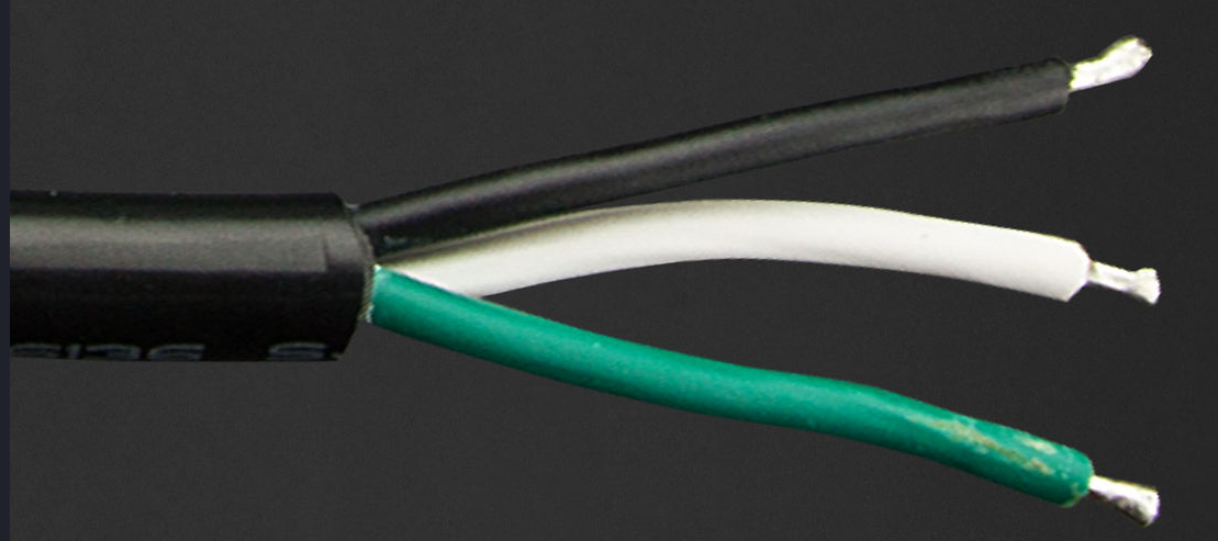
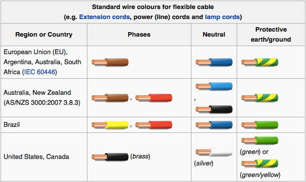
I like to tin the wires so that they they’re easier to securely fasten and to avoid a stray strand of wire touching something it shouldn’t. In the United States, green should be ground and white should be neutral (N) leaving the black as live (L), but you should take a continuity test to be sure. Computer cables are usually labeled on the end that enters the power supply if you want a good reference.
My 5V power supply had labels stamped in the metal above the terminals:
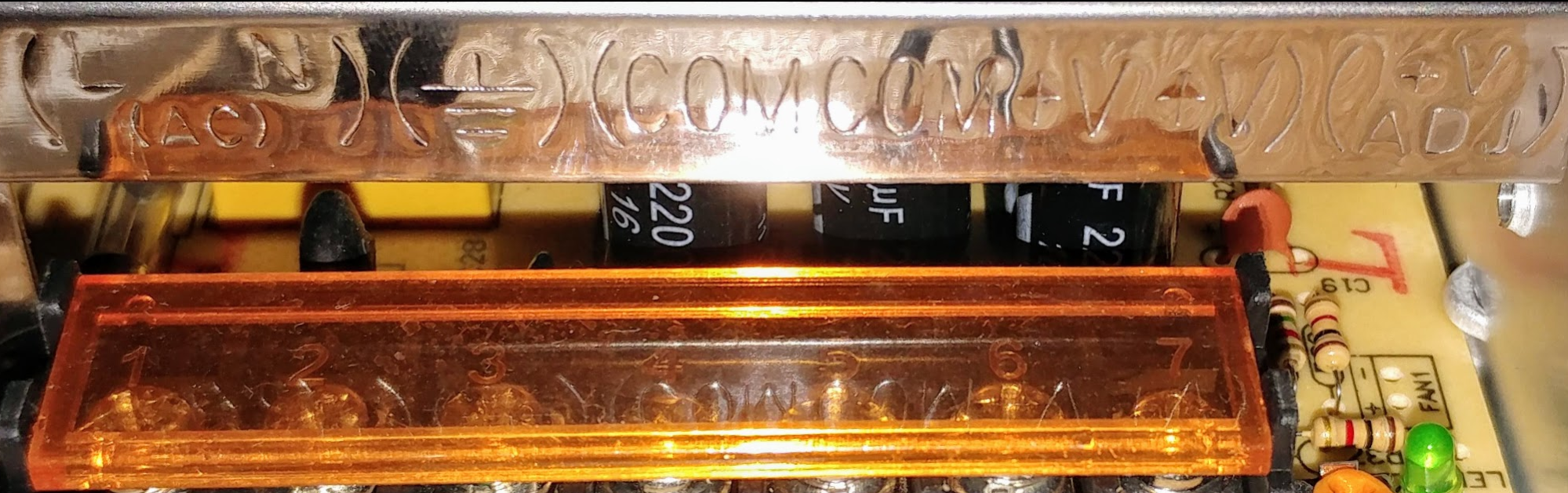
Connect the leads to the terminals, give the cord a tug to make sure they’re secure, and attach mains to into a power strip so you can quickly turn it off if have undesirable results. If there’s no smoke, fizzing, and/or pops, test the power supply with your multimeter. You should be getting approximately 5V across COM and +V. If you’re not, you may have to adjust a potentiometer. Mine didn’t require any dialing in.
Next you’ll want to test your the LED strip. To easily interface with your WS2812b, you’ll want Daniel Garcia’s FastLED library installed in your Arduino IDE. Once installed, upload an example sketch:
#include <FastLED.h>
#define NUM_LEDS 184 //set to the number of LEDs on your strip
#define DATA_PIN 3
CRGBArray<NUM_LEDS> leds;

void setup() {
   	delay(2000);
    FastLED.addLeds<WS2812B, DATA_PIN, RGB>(leds, NUM_LEDS);
}
void loop() {
   for(int whiteLed = 0; whiteLed < NUM_LEDS; whiteLed = whiteLed + 1) {
      leds[whiteLed] = CRGB::White;
      FastLED.show();
      delay(100);
      leds[whiteLed] = CRGB::Black;
   }
}
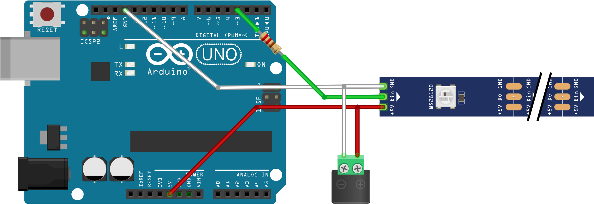
The strip I ordered came with a convenient connector.
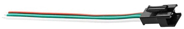
If yours included something like this, I suggest you solder it to your Arduino so you can easily disconnect it from the strip. Red to 5V, white to GND, and green to a 330Ω resistor connected to data pin 3. I just spliced the resistor in and covered it in heat shrink. With your power supply unplugged from mains, you’ll additionally need to attach the the strip’s red wire to the power supply’s +V and the white to COM.
If the sketch was uploaded and you wired everything together correctly, you should be able to disconnect your Arduino from your computer and turn on the 5V power supply. Again, use a power strip just in case anything goes wrong. With any luck, the demo sketch should be illuminating your strip. If it worked, you’re ready to upload this modified Adalight sketch that will allow Hyperion to control the WS2821b strip. If you didn’t install the FastLED library earlier, you’ll need to do so now for the sketch to compile:
⬇️ Adalight.ino
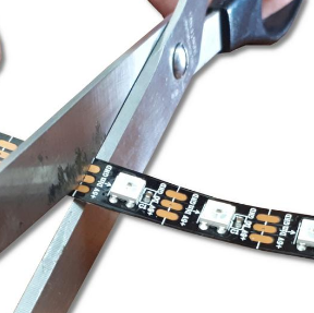
Now comes the tricky part. You need to measure and cut your strip into four segments, two to span the top and bottom of your display and two to span the left and right. It’s best to disconnect the strip and physically place it where you intend to put it on the back of your display housing. There’s no reason for the LEDs to be at the very edge of the housing, but the closer to the edge you can get, the better the results will be. When cutting the strip, be very careful to not damage the copper pads and cut as close to the center as possible leaving room to solder your connecting wires.
Next cut nine wires just long enough to connect the segments at the 90° corner turns. Tin both ends of the wires you cut down as well as the pads on your strip. You may prefer to adhere the strips before you solder, but I chose to solder the four strips together first. I have my display mounted to a wall and was able to apply the segments with minimal difficulty by removing the adhesive film as I went. I found the self adhesive backing perfectly sufficient, but applied some hot glue at the corners and a liberal amount where the strip attaches to power and data for good measure. I went counter-clockwise starting at the bottom right, but the Hyperion configuration tool will accommodate almost any arrangement you can imagine, even gaps.
When you’re happy with your strip segments, reattach the Arduino and power. It’s finally time to install and configure Hyperion. If you’re using Arch Linux, there’s a package in the AUR; otherwise, you can find it on GitHub. After installing, start the Hyperion daemon sudo systemctl start hyperiond and navigate to localhost:8090.
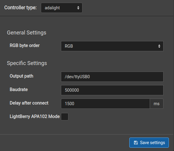
- Set the controller type to “adalight”.
- Set the output path to the same device you uploaded your Aduino sketch to.
- Set the same baudrate used in the Adalight sketch (500000 unless changed).
- Navigate to the “LED Layout” tab and make it consistent with your arrangement.
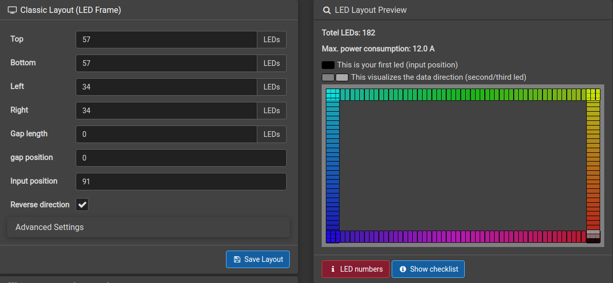
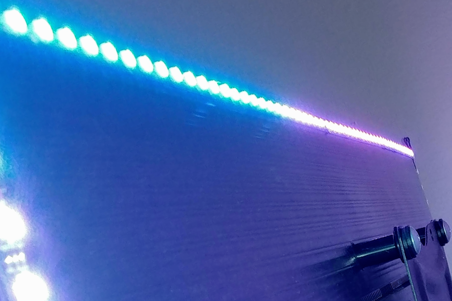
Notice, I had to reverse the orientation and set the input position to 91. Don’t forget to save your layout. The last step is launching the hyperion-x11 client. Hope it works! Here’s a colorful video to test your setup: